- 1. Pre-Installation Site Assessment
- 2. Solar Street Light Pole Height Selection
- 3. Spacing Between Solar Street Lights
- 4. Solar Panel Angle and Orientation
- 5. Foundation and Mounting Requirements
- 6. Battery Placement and Temperature
- 7. Wiring and Controller Setup (Split-Type)
- 8. Commissioning and Testing Checklist
- 9. What Solar Street Light Installation Mistakes We See Most

We shipped our first solar street light in 2014. Back then, most installations failed within 18 months, usually because the pole height, panel angle, or battery enclosure was wrong. The technology has improved significantly since then, but installation errors remain the number one cause of system failure. Roughly one in three support calls we receive traces back to an installation mistake, not a product defect. The hardware is reliable. The installation usually is not. Get the pole height, spacing, or panel angle wrong, and you end up with dim lights, dead batteries, and a project that costs more to fix than it saved.
At our factory, we have shipped solar street lights to over 200 projects across 30 countries. Across those projects, the most common culprits behind failures are undersized foundations, wrong panel tilt, and spacing that is too wide for the road.
Below is the installation sequence our engineers follow on every project, from site visit to commissioning. Whether you are installing all-in-one solar street lights or split-type systems, the principles below apply. Before you dig the first hole, run your project numbers through our Solar Light Calculator to size panels, batteries, and fixtures for your location.
1. Pre-Installation Site Assessment
Every solar street light installation begins with a site visit. Skipping this step is the single most expensive shortcut in the industry. A site that looks fine on Google Maps can hide shading, poor soil, or a microclimate that kills battery performance. Three variables matter most: sunlight hours, shading, and road width.
Sunlight Hours (Peak Sun Hours)
Solar street lights depend on the daily peak sun hours (PSH) available at the location. PSH is not the same as daylight hours; it is the equivalent number of hours of full 1000 W/m2 solar irradiance. A site with 12 hours of daylight may only receive 3.5 PSH if it is cloudy or hazy. Use local solar irradiance data from NASA POWER or PVGIS to find the worst-case winter PSH, because the system must survive the shortest, cloudiest days of the year. As a rule of thumb, you want a minimum of 3 PSH in the design month. Below that, the panel and battery must be oversized significantly, which raises cost.
Shading Analysis
Walk the site at three times of day: 9 AM, noon, and 3 PM. Look for trees, buildings, hills, or overhead power lines that cast shadows across the planned pole locations. Even partial shading on a solar panel can cut output by 30-50%, because cells are wired in series and one shaded cell drags down the whole string. If a pole location is shaded for more than 2 hours of peak sun, move it or trim the obstruction. For split-type lights, the panel can be mounted separately from the lamp head, which gives more flexibility to position the panel in a clear-sun zone.
Road Width and Layout
Measure the road width including shoulders. Road width determines pole height, fixture wattage, and whether you need single-sided or staggered (zigzag) layout. As a guide: roads under 8m wide can use single-sided mounting; roads 8-15m wide benefit from staggered mounting on both sides; roads over 15m require opposite (double-sided) mounting for uniform coverage. Record the road length, number of intersections, curves, and any existing infrastructure that poles must avoid, such as drainage culverts or buried utilities.
Document all findings in a site report with photos and GPS coordinates for each proposed pole. This report becomes the basis for your ROI calculation and your installer's work order.
2. Solar Street Light Pole Height Selection
Pole height is the foundation of your lighting design. It controls how far the light spreads, how bright the road surface appears, and how much glare drivers and pedestrians experience. Choose the wrong height and you either waste money on a pole that is too tall or end up with dark patches from a pole that is too short.
The general principle: taller poles cast light over a wider area but with lower surface illuminance per square meter. Shorter poles concentrate light but cover less ground. Match pole height to road type and traffic speed. Faster traffic needs taller poles with more throw; slower residential traffic needs shorter poles with softer, more uniform light.
| Road Type | Pole Height | Spacing | Recommended Wattage |
|---|---|---|---|
| Residential street / walkway | 6 m | 15-18 m | 30-60 W |
| Secondary urban road | 8 m | 20-24 m | 60-100 W |
| Main urban road | 10 m | 25-30 m | 100-150 W |
| Highway / expressway | 12 m | 30-36 m | 150-300 W |
| Parking lot / plaza | 8-10 m | 20-30 m | 80-120 W |
- 6 m: Residential streets, walkways, parks, bike paths
- 8-10 m: Main urban roads, commercial areas, parking lots
- 12 m: Highways, expressways, large intersections
- Wall thickness: 2.5-3.0 mm for 6m poles; 3.0-4.5 mm for 12m poles
- Material: Hot-dip galvanized steel, powder-coated for corrosion resistance
For residential streets, a 6m pole with a 30-60W LED head delivers 15-20 lux on the road surface, which is the IES-recommended level for local streets. IES RP-8 (Recommended Practice for Roadway Lighting) defines the illuminance targets referenced in this guide. Going taller than 6m on a narrow residential road wastes light and creates harsh shadows at the property line. For main urban roads carrying vehicle traffic at 40-60 km/h, an 8-10m pole lifts the beam to cover a 20-30m span while keeping glare below the threshold that distracts drivers.
For highways, 12m poles are standard. The extra height lets the beam reach across multiple lanes, and the higher mounting angle reduces direct glare into oncoming windshields. But 12m poles demand a heavier foundation and a more powerful LED head (150W+), because light intensity drops with the square of distance. A 100W head that is bright at 8m looks dim at 12m unless the optical lens is designed for long throw.
Always specify the pole's wind load rating. A 12m pole acts like a sail in a storm. In coastal or typhoon-prone regions, specify poles rated for at least 150 km/h wind speed and increase the foundation accordingly.
3. Spacing Between Solar Street Lights
Once pole height is set, spacing follows a simple rule of thumb: space solar street lights 2.5 to 3 times the pole height apart. This ratio balances uniform illumination with cost efficiency. Closer spacing produces more uniform light but uses more poles and fixtures; wider spacing saves money but can leave dark gaps between fixtures.
For an 8m pole, that means 20-24m between poles. For a 6m residential pole, 15-18m. For a 12m highway pole, 30-36m. The lower end of the range (2.5x) is used where uniformity matters most: curves, intersections, pedestrian crossings, and high-crime areas. The upper end (3x) is acceptable on long straight stretches of low-traffic road where minor dimming between poles is tolerable.
Single-Sided vs. Staggered vs. Opposite Layout
On narrow roads (under 8m wide), single-sided mounting works: all poles on one side, light throws across the full road width. On medium roads (8-15m), staggered (zigzag) mounting on alternating sides gives better uniformity and eliminates the dark far-side edge that single-sided creates. On wide roads (over 15m), opposite mounting places poles directly across from each other so each side illuminates its half of the road.
At intersections, add a dedicated pole at the corner to light the conflict zone where vehicles and pedestrians cross. Do not rely on the regular spacing to cover intersections, because the geometry changes and standard spacing leaves the crossing underlit.
One caution specific to solar: because each pole is an independent power unit, spacing errors cannot be compensated by re-aiming a shared grid fixture. If a gap is too wide, the only fix is adding a pole, which means another foundation, another fixture, and another cable run to the controller. Get spacing right the first time.
4. Solar Panel Angle and Orientation
The solar panel angle is the single biggest determinant of how much energy your street light harvests, and it is the most frequently mis-set parameter on site. A panel tilted 15 degrees off the optimal angle can lose 10-15% of annual yield. Tilted 30 degrees off, it can lose 25%.
Tilt Angle (Latitude-Based)
The optimal year-round tilt angle equals the local latitude. At 30 degrees latitude (for example, Houston or Cairo), tilt the panel 30 degrees from horizontal. At 45 degrees latitude (Paris or Portland), tilt 45 degrees. This setting balances summer and winter production so the battery charges adequately in the low-sun winter months when lighting demand is highest.
If your region has long cloudy winters, add 10-15 degrees to the latitude angle. The steeper tilt favors winter sun, which is lower on the horizon, and helps the panel self-clean by letting rain and snow slide off. If your region is summer-dominant and winters are mild, subtract 5-10 degrees to favor the higher summer sun. For equatorial regions within 10 degrees of the equator, a fixed 10-15 degree tilt is standard, primarily for rain runoff rather than sun tracking.
Orientation (Facing South / North)
In the northern hemisphere, face the panel due south (azimuth 180 degrees). In the southern hemisphere, face it due north. Deviation from true south by more than 15 degrees east or west measurably reduces daily harvest. Use a compass corrected for local magnetic declination, or better, use a GPS app that reports true north. Many installers set panels facing the road for aesthetics; this is wrong if the road does not run the correct direction. Energy output comes first.
- Year-round tilt: Equal to local latitude
- Cold-winter tilt: Latitude + 10-15°
- Mild-winter tilt: Latitude - 5-10°
- Orientation (N. Hemisphere): True south, azimuth 180°
- Orientation (S. Hemisphere): True north, azimuth 0°
- Max azimuth deviation: ±15° from optimal
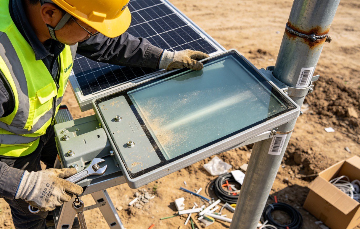
For all-in-one solar street lights, the panel is factory-fixed at a set angle on the lamp housing. In that case, choose a model whose fixed angle matches your latitude, or order a custom tilt. For split-type lights, the panel mounts on its own bracket, so you can fine-tune the angle on site with an inclinometer. Take five extra minutes per pole to verify the angle; it pays back across every night of the system's 5-10 year life.
5. Foundation and Mounting Requirements
The foundation is what keeps a solar street light standing through years of wind, rain, and frost. An undersized foundation is the most common cause of pole tilt and eventual collapse. Foundation design depends on pole height, soil bearing capacity, local wind load, and frost line depth.
Concrete Base Depth and Dimensions
For a 6m pole, dig a foundation hole 0.8-1.0m deep with a 0.6 x 0.6m base. Pour C25 or higher grade concrete and embed a flange plate or anchor bolts to match the pole base. For an 8-10m pole, increase to 1.2-1.5m deep with a 0.8 x 0.8m base. For a 12m highway pole, go 1.5-2.0m deep with a 1.0 x 1.0m base. The foundation should extend below the local frost line so freeze-thaw cycles do not heave the concrete and tilt the pole.
Use a steel reinforcing cage (rebar) inside the concrete for poles over 8m. The cage prevents the concrete from cracking under wind-induced bending moments. Embed a ground rod for lightning protection on taller installations; a 12m metal pole on an open road is a lightning target.
Wind Load Considerations
Wind load drives foundation size more than pole weight does. A solar street light presents a large surface area to the wind: the panel, the lamp head, and the pole itself. The projected area of a 100W panel plus lamp head on a 12m pole can generate 800+ N of lateral force in a 120 km/h gust. The foundation must resist that force as a bending moment at the base. In typhoon or hurricane zones, increase foundation depth by 20-30% and specify poles rated for the local design wind speed.
- 6m pole: 0.8-1.0m deep, 0.6 x 0.6m base, C25 concrete
- 8-10m pole: 1.2-1.5m deep, 0.8 x 0.8m base, C25 + rebar cage
- 12m pole: 1.5-2.0m deep, 1.0 x 1.0m base, C30 + rebar + ground rod
- Cure time: 72 hours minimum before pole erection
- Frost line: Foundation base must sit below local frost depth
Allow the concrete to cure for at least 72 hours before erecting the pole. Rushing this step is a common cause of loose anchor bolts and tilted poles. In cold weather, cover the pour with insulation blankets and use antifreeze admixture so the concrete reaches design strength.
6. Battery Placement and Temperature Considerations
The battery is the heart of a solar street light. It stores the day's harvest and powers the lamp through the night. Where and how you mount it directly affects lifespan, which in turn drives total cost of ownership. A lithium battery that should last 5-8 years can die in 2 if it is mounted in a hot, poorly ventilated enclosure.
Placement Options
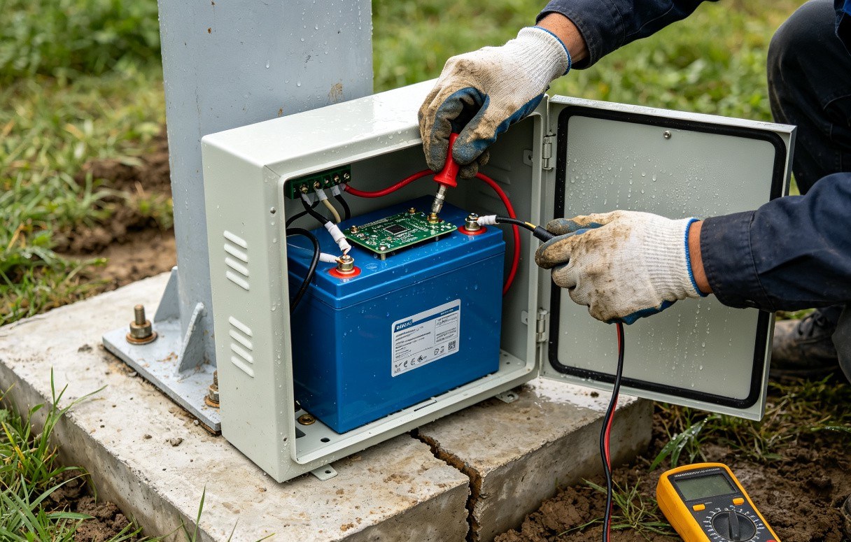
For all-in-one solar street lights, the battery is integrated into the lamp head at the top of the pole. This is convenient and theft-resistant, but it exposes the battery to the highest temperatures on the site, since heat rises and the lamp head bakes in the sun all day. For split-type lights, the battery is typically mounted in a separate enclosure at the base of the pole or mid-pole inside the pole shaft. Base mounting keeps the battery cooler and makes it accessible for maintenance, but it is more vulnerable to theft and flooding.
Temperature Effects on Battery Life
Lithium iron phosphate (LiFePO4) batteries, the standard for solar street lights, perform best between 0°C and 45°C. Above 45°C, chemical degradation accelerates and cycle life drops sharply. For every 10°C above the optimal range, battery life roughly halves. A battery mounted in a sealed black box at the top of a pole in a desert climate can hit 65-70°C internally, cutting a 2000-cycle battery down to under 800 cycles. Below 0°C, charge acceptance drops and the battery cannot be fully recharged, which leads to sulfation in lead-acid or lithium plating in lithium-ion.
In our lab testing, a LiFePO4 battery cycled at 55°C enclosure temperature reached 800 cycles before dropping to 80% capacity. The same battery at 35°C reached 2,100 cycles. That is the difference between a 3-year lifespan and a 7-year lifespan.
To mitigate heat: choose enclosures with ventilation louvers or a heat-dissipating fin design, paint the enclosure white or light gray to reflect solar gain, and for split-type systems, mount the battery at the pole base where ground temperature is more stable. In cold climates, specify a battery heater pad for temperatures below -10°C, and size the panel larger to compensate for reduced winter charge efficiency.
7. Wiring and Controller Setup for Split-Type Lights
Split-type solar street lights have separate components: panel, lamp head, battery, and controller. Wiring these correctly is critical, because reversed polarity or a missing connection can destroy the controller or the battery on the first power-up.
The standard wiring sequence is: connect the battery to the controller first, then the solar panel, then the LED load. This order matters. The controller needs battery power to initialize before it can regulate the panel input. If you connect the panel first, the controller may receive unregulated voltage and fail. Most modern controllers are protected against this, but following the sequence is still best practice.
- Battery connection: Connect battery positive and negative to the controller's battery terminals. Observe polarity; reversed connections blow the controller fuse or damage the unit permanently.
- Solar panel connection: Connect panel output to the controller's solar terminals. Use MC4 connectors for waterproof, tool-free mating.
- LED load connection: Connect the lamp head to the controller's load terminals. The controller switches the lamp on and off based on its light sensor and timer settings.
- Wire gauge: Use appropriately sized cable to limit voltage drop. For runs over 3m between panel and controller in a split system, use 2.5 mm2 or thicker copper cable.
The controller is the brain of the system. It manages charging (preventing overcharge and deep discharge), controls the light output mode (full brightness, dimming, motion-sensor boost), and protects the battery. Configure the controller settings to match your project: set the autonomy days (typically 2-3 nights of battery reserve for cloudy periods), the dimming schedule (e.g., full brightness for the first 4 hours, then 50% until dawn), and the motion sensor sensitivity if applicable. Modern controllers with MPPT (Maximum Power Point Tracking) harvest 20-30% more energy than older PWM controllers, especially in cloudy conditions, so specify MPPT for any project with marginal sun hours.
8. Commissioning and Testing Checklist
Commissioning is the final verification that every component is installed correctly and the system performs as designed. Do not hand a project over without completing every item on this checklist. A system that works on a sunny test day can still fail on the first cloudy night if the battery was never validated.
- Pole verticality: Use a spirit level on two axes. Tolerance: <1 degree from vertical.
- Panel orientation: Verify azimuth (true south/north) and tilt angle with an inclinometer. Tolerance: ±5 degrees.
- Foundation integrity: Confirm concrete is fully cured and anchor bolts are torqued to spec.
- Battery voltage: Measure open-circuit voltage at the controller. Confirm it is within the charged range before first power-up.
- Wiring polarity: Double-check positive and negative on all three controller connections (battery, panel, load).
- Controller settings: Confirm charging mode (MPPT/PWM), autonomy days, dimming schedule, and motion sensor parameters are configured correctly.
- Charging test: On a sunny day, confirm the controller shows charging current and battery voltage rises over 2-3 hours.
- Night test: Cover the panel to simulate darkness. Confirm the lamp turns on automatically at the set brightness.
- Autonomy test: If feasible, run the system for 2-3 consecutive cloudy days and confirm the lamp still operates at full schedule on the third night.
- Illuminance measurement: Measure lux on the road surface at the midpoint between two poles. Confirm it meets the design target (e.g., 15-20 lux for residential, 30+ lux for main roads).
- Photocell / timer: Verify the lamp turns off at dawn and the controller returns to charging mode.
Document each test result with a photo or reading. This record protects you against warranty disputes later. If the client reports a dim light six months in, you can refer back to the commissioning lux reading to determine whether the problem is component degradation or an environmental change (new shading from tree growth, dirt on the panel, etc.).
9. What Solar Street Light Installation Mistakes We See Most
Most solar street light failures are preventable. After supporting hundreds of installations, these are the errors we see again and again. Review this list with your installer before breaking ground.
- Wrong panel tilt. Setters eyeball the angle instead of using an inclinometer. A 20-degree error can cut winter harvest by 25%, which means the battery dies by 2 AM in January. Always verify with a tool.
- Panel facing the wrong way. Installers orient panels to face the road for looks rather than true south/north. Aesthetics over function kills energy yield. Energy first, aesthetics second.
- Undersized foundation. To save concrete cost, crews dig shallow holes. The pole stands for a year, then tilts after the first storm. Redoing a tilted pole costs 5x the concrete you saved.
- Spacing too wide. Stretching spacing beyond 3x pole height to cut fixture count leaves dark gaps. The fix is adding poles, which costs more than doing it right initially.
- Battery in a hot enclosure. Top-mounted batteries in dark enclosures overheat and die in 2 years instead of 6. Specify ventilated or light-colored enclosures, or use split-type with base mounting in hot climates.
- Skipping the wiring sequence. Connecting the panel before the battery can fry the controller. Follow battery-panel-load order every time.
- No commissioning test. The crew leaves before verifying night operation. The first failure is discovered by the end user, not the installer. Always run a night test before handover.
- Ignoring the frost line. In cold climates, foundations above the frost line heave and tilt poles over winter. Dig to below the local frost depth, full stop.
- Mixing controller brands on dimming circuits. If you network multiple poles for synchronized dimming, use one controller brand. Mixed protocols cause erratic behavior.
Each mistake on this list has a cheap prevention and an expensive cure. Spend the extra hour on site assessment, foundation depth, panel angle verification, and commissioning. That hour is the difference between a project that runs maintenance-free for 8 years and one that generates a complaint call every rainy season.
Frequently Asked Questions
Pole height depends on road type. Use 6m poles for residential streets and walkways, 8-10m poles for main urban roads, and 12m poles for highways and expressways. Taller poles cover a wider area but require more powerful fixtures and stronger foundations to handle wind load.
Solar street lights should be spaced 2.5 to 3 times the pole height apart. For example, an 8m pole needs 20-24m spacing. Closer spacing (2.5x) is used on curves, intersections, and high-traffic areas for uniform coverage; wider spacing (3x) works on straight, low-traffic roads to reduce fixture count and project cost.
Tilt the solar panel at an angle equal to the local latitude, plus 5-15 degrees in winter-dominant regions. In the northern hemisphere, face panels due south; in the southern hemisphere, face due north. For example, at 30 degrees latitude, a 30-35 degree tilt maximizes year-round energy harvest.
Foundation depth depends on pole height and soil type. For a 6m pole, dig 0.8-1.0m deep with a 0.6x0.6m base. For 8-10m poles, dig 1.2-1.5m deep with a 0.8x0.8m base. For 12m highway poles, dig 1.5-2.0m deep with a 1.0x1.0m base. Always account for local wind load and frost line depth.
Size your solar street light project
Free solar light calculator based on your location's peak sun hours, road width, and lighting requirements. Get panel, battery, and fixture sizing instantly.
What This Changes for Your Next Project
Solar street light installation is a sequence of interdependent decisions. Pole height sets the spacing. Spacing sets the fixture count. The panel angle sets the energy harvest. The foundation sets whether the pole stands for a decade or tilts in the first storm. Get each link in the chain right, and the system runs maintenance-free for years. Get one wrong, and the whole chain weakens.
At Tonghua Lighting, we manufacture solar street lights for projects ranging from single residential lanes to multi-kilometer highway installations. Every shipment includes a site assessment template, a commissioning checklist, and controller configuration support. The guidelines in this article are the same ones our engineers use on every project, because they are what separate a system that lasts from one that fails.
On a 2024 project for a 2.3 km rural road installation in the Philippines, we specified 8m poles at 22m spacing with 80W LED heads. The system survived Typhoon Carina in July 2024 with zero pole failures, because the foundation was sized for 150 km/h wind load and the panel tilt was verified with an inclinometer on every pole.
Before you order fixtures, run your road dimensions and location through our Solar Light Calculator and check the project economics with the ROI Calculator. The numbers will tell you whether solar beats grid lighting for your site, and they will size every component before you spend a dollar on hardware. Then follow the installation steps above, and your lights will turn on the first night and stay on for years.